Making an ATX Breakout Board
Although I love software and write it for fun and profit, I have also started to fall in love with electronics. I’ve mostly only fiddled around with PIC chips and 555 timers on a breadboard, but this time I went more permanent. I decided to make an ATX breakout board. The idea is to turn any PC power supply into a usable bench supply.
This is handy because the ATX protocol offers a lot of different voltages. While it’s not as nice as an adjustable supply, it can be made with stuff you probably have on hand if you dabble in electronics.
Here is a GIANT disclaimer. I’m no electrical engineer. I write software and I don’t claim to really know what I’m doing at all. I am learning. What I’ve done here is probably extremely unsafe. But, it was fun and it works.
The first thing I did was check out the ATX pin-out, and read up about it to figure out if there was anything special I needed to know.

Turns out that there are two different ATX protocols. Version 1 has 20 pins and version 2 has 24. They are compatible, in that the 4 extra pins just don’t exist in version 1, but lay out the same.
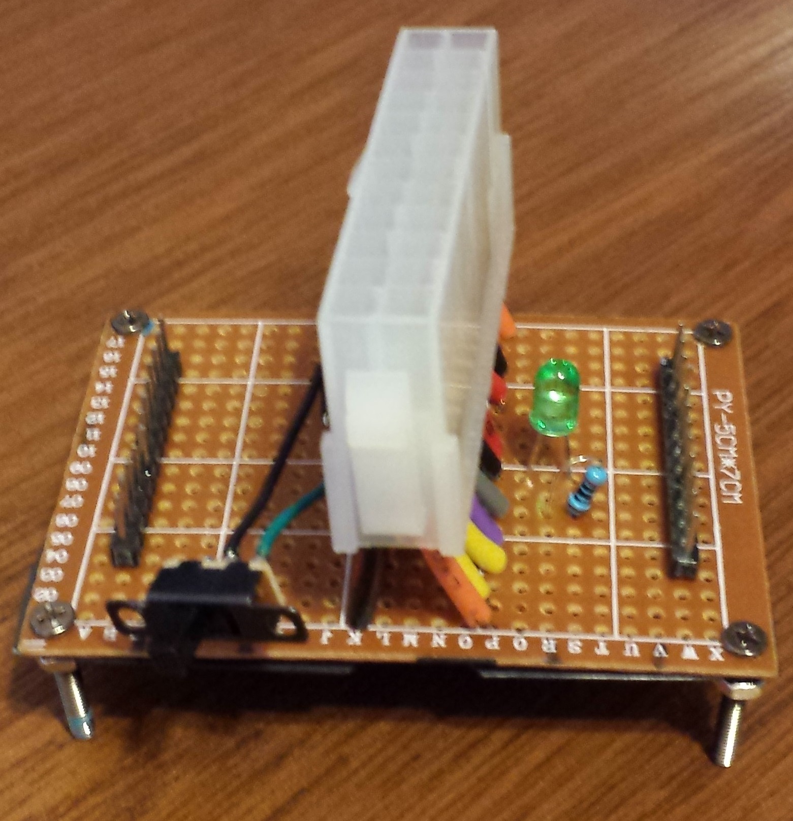
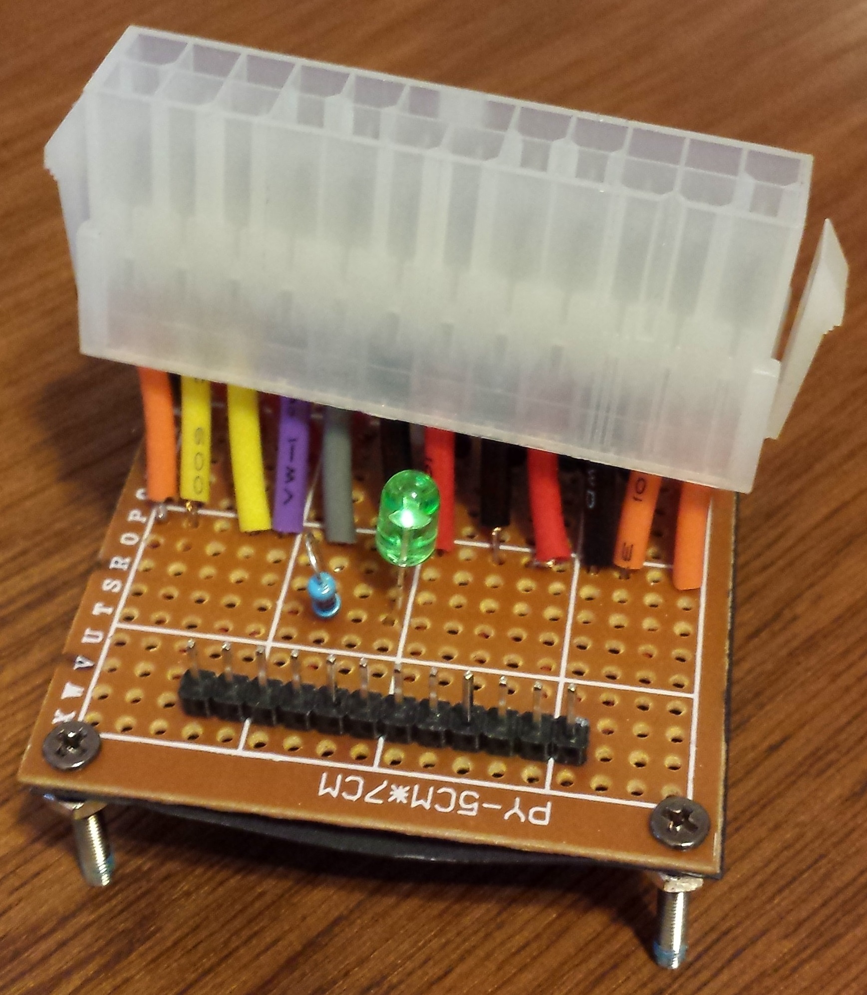
The pins are pretty straight forward. To turn on the supply, you need to short the PS_ON pin to COM and the PWR_OK pin gives 5V once everything is running. I wired a switch between PS_ON and COM and I used PWR_OK to light an LED.
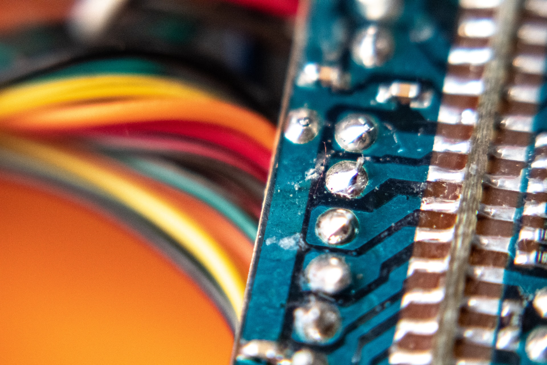
Next, I had an ATX extension cable, so I cut it and soldered the socket side to a prototype board. I wish I had given myself some more length from the wires. It was kind of a nightmare to strip, tin and get all 24 pins through the holes of the board.
After that, I added the switch and tested it out. Check out this shaky video:
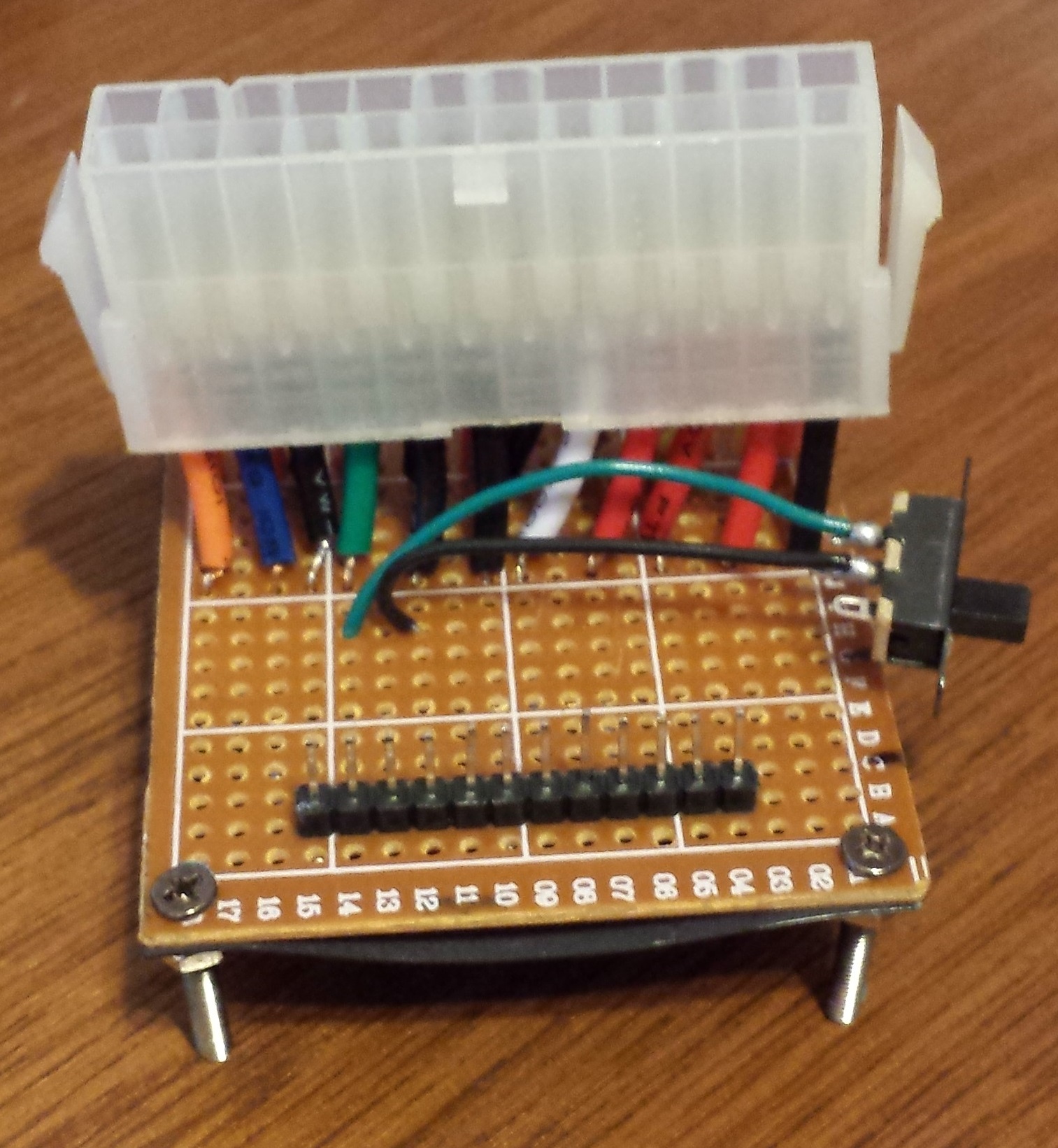
Once I had that in, I soldered in some pin headers and jumpers from the sockets to the headers. I tried this two different ways. First I tried just soldering one header pin to the board, then solder the jumper to the pin at the same time. This was difficult as I didn’t have a good way to hold the jumper down while soldering.
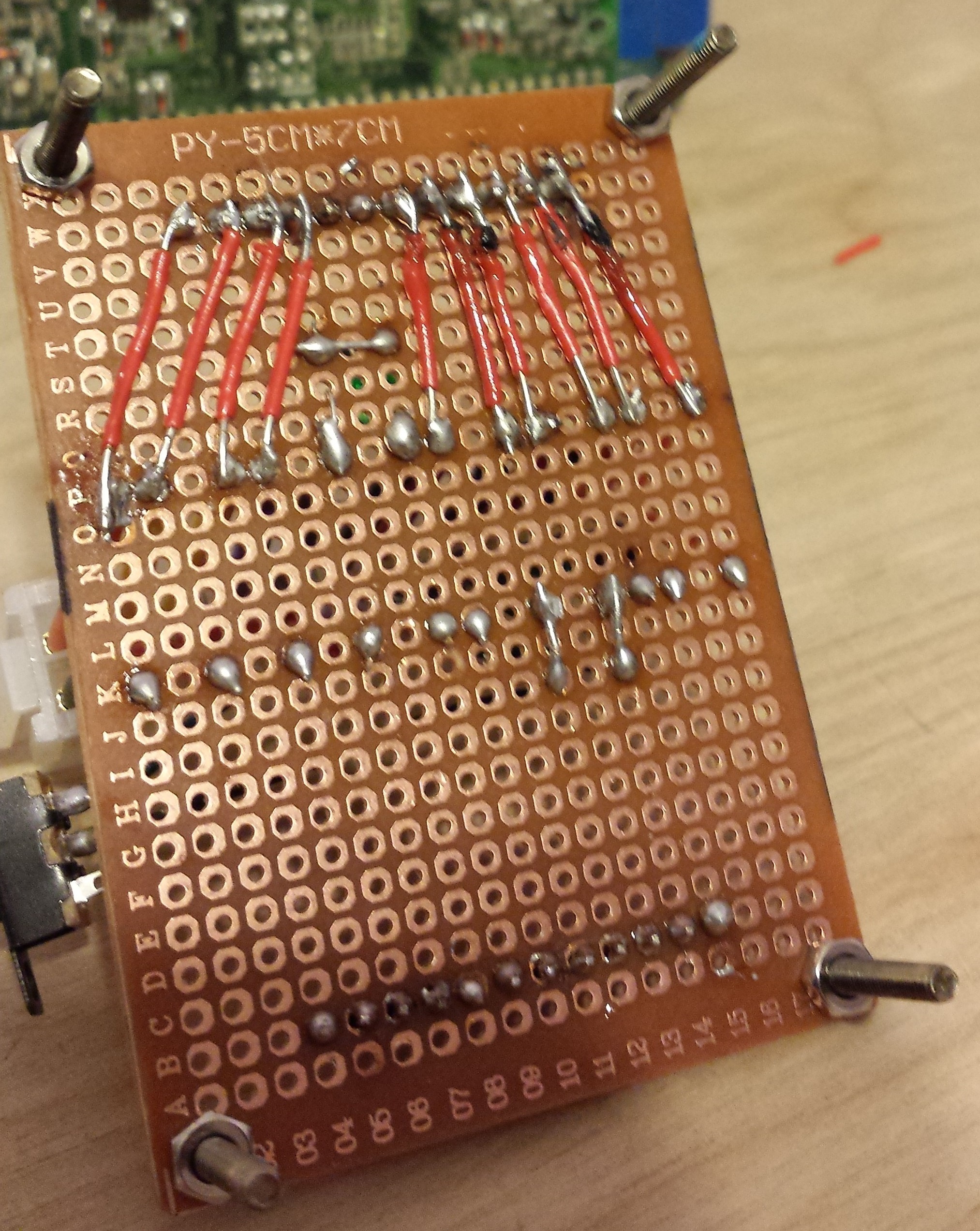
The second way was a bit easier. I soldered all the headers in, then re-melted the solder and stuffed the jumper into it and pulled away the iron until it cooled. This made things faster, but don’t forget that the wire can get hot.
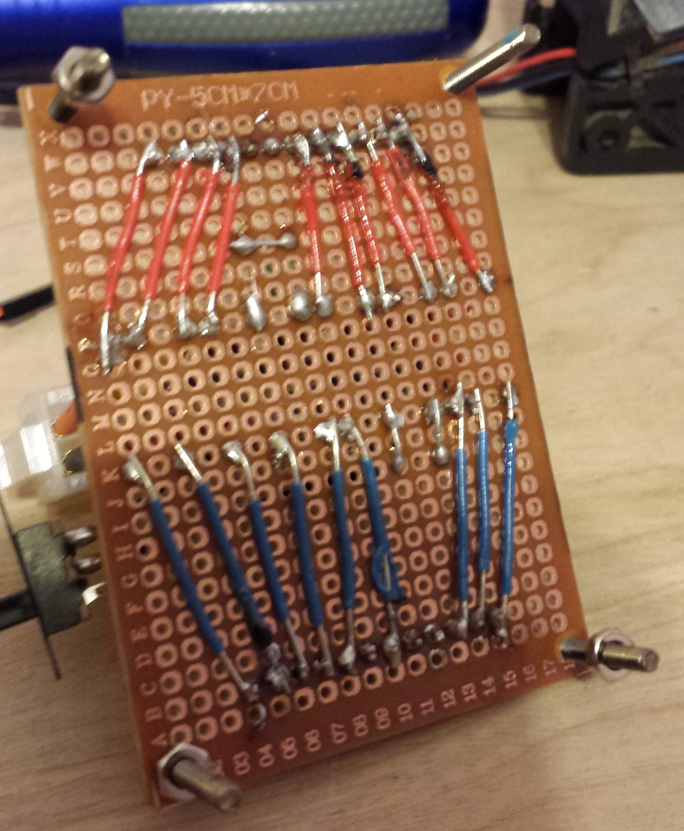
Once you’re done drooling over my NASA level soldering skills (sarcasm), you’ll notice I didn’t jump all the pins across. I didn’t bother bringing the switch and LED pins across, and when stripping the wires on the socket, I completely yanked out a COM pin in the middle of the blue side.
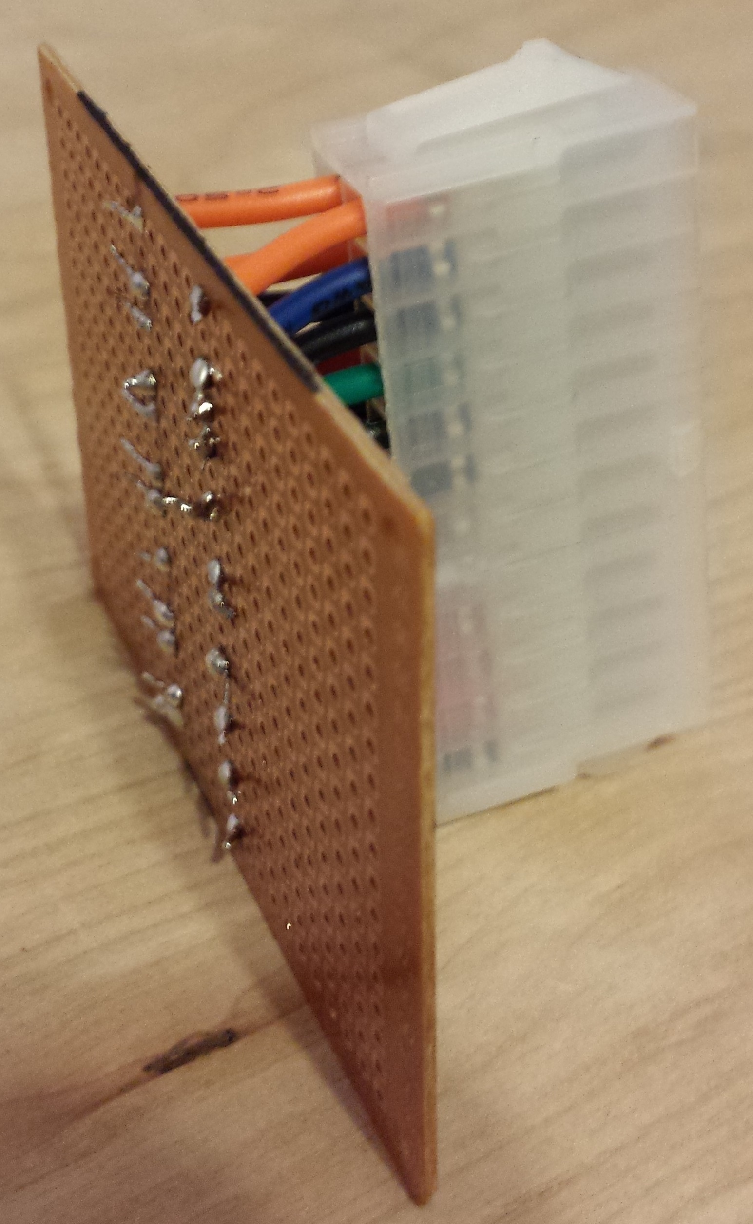
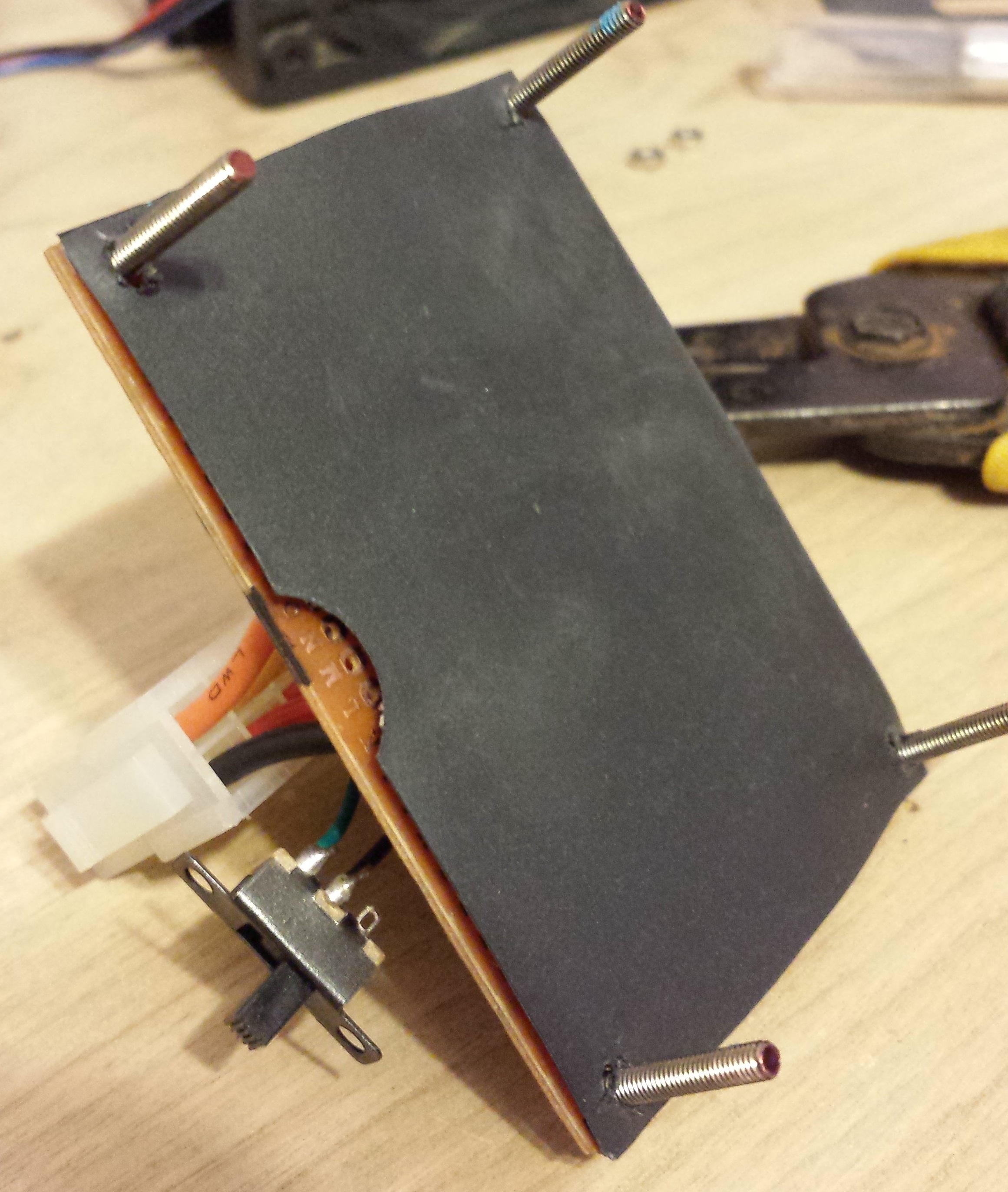
I had found some insulating, plastic-ish paper from an old piece of electronics I took apart and a few screws with nuts included. I used the screws as stand-offs and put the paper under the board to try and minimize bare wire exposure.
And finally, here are a couple images of the switch and LED sides of the board:
This was a fun little project with plenty of frustrating soldering. I’m still kind of new to soldering so this was a good challenge. I only burned myself probably a dozen times in the process. I’ll finish this post up with a video of it powering a 12V DC fan that looks like it could be used for a hovercraft.